Oil Water Separator Design Calculation

11 2 description oil water separators are typically the american petroleum institute.
Oil water separator design calculation. 130 water temperature f 65d typical qm ah 7 48 2 1 072 x 10 6 s w s 0 95 specific gravity of the oil s g g cm3 q m design flow in m 3 hr 150 oil droplet size to be removed in microns 30 microns typical ah horizontal separator area in m 2 0 75. This chapter provides a discussion of their application and design criteria. The spreadsheet operates on microsoft excel 2003 or later. The slower the flow the better the results.
Oil water separators sizing guide for your convenience highland tank s oil water separator ows sizing utilities are available on line at. One of the design parameters for an oil water separator is the minimum size of oil droplet removed from the waste water stream. The design flow for an ows should be based on the maximum total flow rates projected for treatment of contaminated flow at any given time. Below is a sample shot of the spreadsheet.
Therefore the effectiveness of any oil water separator is affected by the flow rate. Design capacity an oil water separator has upper limits to the amounts of oil and sludge that can effectively accumulate while it is in operation. Oil water separators remove oil and other water insoluble hydrocarbons and settleable solids from stormwater runoff. Api separator calculations density of the water in g cm3 temp f absolute viscosity kinematic viscosity centipoises centistokes ssu ft sec poise density g cm3 viscosity in poise temperature in deg f design oil droplet in cm terminal velocity in cm s oil droplet size in microns specific gravity of the oil in g cm3 terminal.
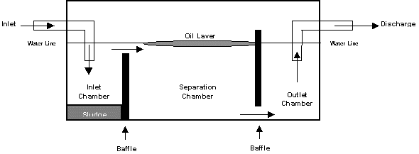
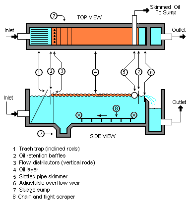
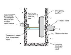
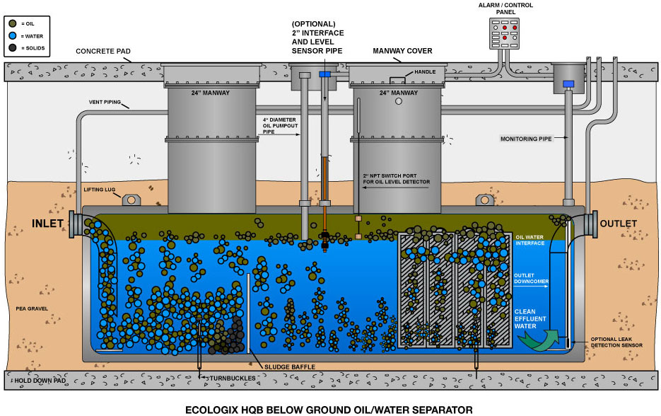
Oil water separator industrial facilities tank farms process drains outfalls. Overall oil water separator system designs are discussed and recommendations for ensuring system efficiency regulatory compliance reliability sustainability and effective procedures are presented. Most of the suspended solids will settle to the bottom of the separator as a sediment layer the oil will rise to top of the separator and the wastewater will be the middle layer between the water on top and the solids on the bottom. Store oil recovered by the separation process and all other equipment or containers at a regulated facility that do not qualify for the wastewater treatment exemption are required to meet the applicable spcc requirements 67 fr 47069 july 17 2002.
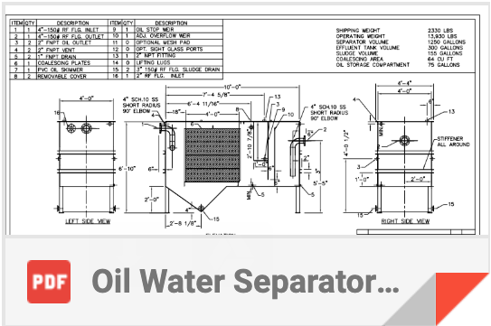
By inputting the major design criteria you can solve for the separation chambers width to length to depth ratios. Based on that design critrion. Bmps are described for baffle type and coalescing plate separators. 2 spill capacity.
The design of the separator is based on the specific gravity difference between the oil and the wastewater because that difference is much smaller than the specific gravity difference between the suspended solids and water. Below is a link to an api oil water separator sizing spreadsheet developed by hydro flo technologies.
